From Handmade Prototype to Factory-Ready Silicon
Evolving from a hand-built ESP32 prototype into a compact, factory-ready RP2354A-based device, with a redesigned PCB, power system, and hardware architecture.
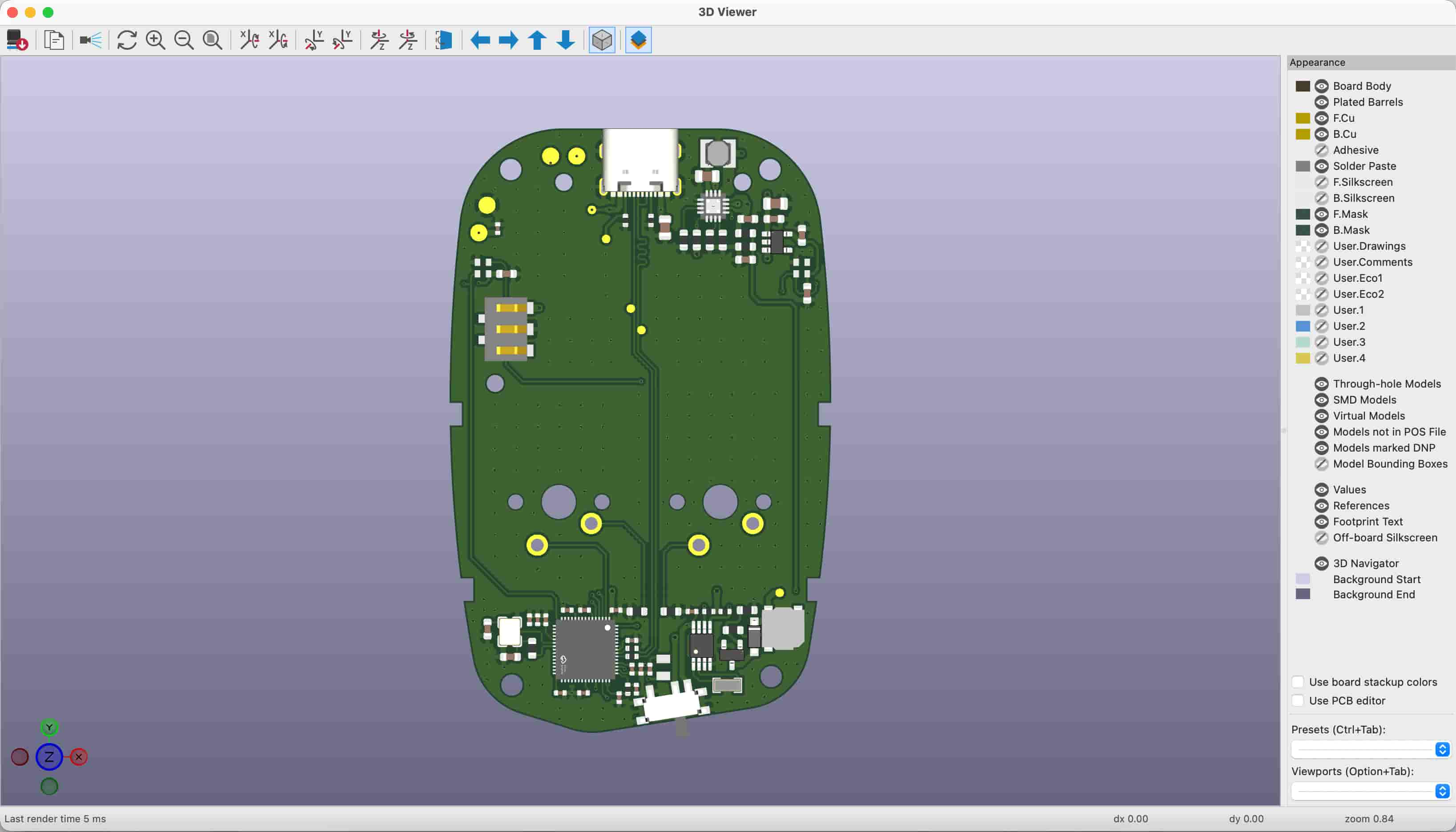
When I started building Click, my primary goal was to create a tactile desk companion that helps quiet your mind through physical interaction. My background is rooted in mechanical design, plastic enclosure ergonomics, and CAD modeling. I can design plastic housings, tune tactile button switches, and model sleek enclosures all day long, but when it comes to electrical circuit design and embedded C++ programming, I rely completely on AI prompts to guide my decisions.
The first physical hardware version, Click 1, was built using the ESP32-WROOM-32E module. I chose the ESP32 because it was readily available and easy to solder onto basic prototype boards for initial testing. It served its purpose well during early software development, powering our first OLED screens and button debounce state machines. However, as the physical prototype evolved, the limitations of Click 1 became obvious.
The ESP32 module was physically large and consumed significant space inside the enclosure. It required a separate CH340 USB-to-UART bridge chip on the board, which added component count and routing complexity. Furthermore, Click 1 lacked a clean physical power kill switch, meaning the battery would slowly drain even when the device was not in active use.
To solve these problems, I redesigned the hardware for Click 4, transitioning to the Raspberry Pi RP2354A microcontroller in a compact QFN-56 package. The RP2354A is a massive step forward for our hardware footprint. It includes 2MB of co-packaged stacked QSPI flash directly inside the silicon package itself. By stacking the flash memory inside the chip, we can completely eliminate external memory chips, decoupled bypass capacitors, and high-frequency memory bus traces from the PCB layout.
For power management, Click 4 incorporates an AP2112K 3.3V low-dropout linear regulator where the physical SPDT slide switch connects directly to the regulator enable pin. When switched off, the regulator output is forced to ground, completely shutting down the 3.3V rail and achieving a true zero milliamp standby leakage from the 400mAh LiPo battery. The ETA charger IC remains connected to the raw battery line, allowing USB charging to function safely even while the slide switch is completely turned off.
I also added dedicated hardware indicators and feedback mechanisms to Click 4. Two addressable WS2812 LEDs are mounted symmetrically as top diffusers to provide smooth breathing animations during charging. A magnetic piezobuzzer driven by an MMBT3904 NPN transistor provides crisp tactile audio clicks at 4000Hz without pulling power from the regulated 3.3V bus.
All schematics, KiCad PCB files, and 3D STEP models for Click 4 are archived in my GitHub repository and prepared for turnkey fabrication and assembly through JLCPCB. By moving from a hand-soldered prototype to automated factory assembly, Click has evolved into a reliable, open-source hardware platform that anyone can reproduce and customize.
Related posts
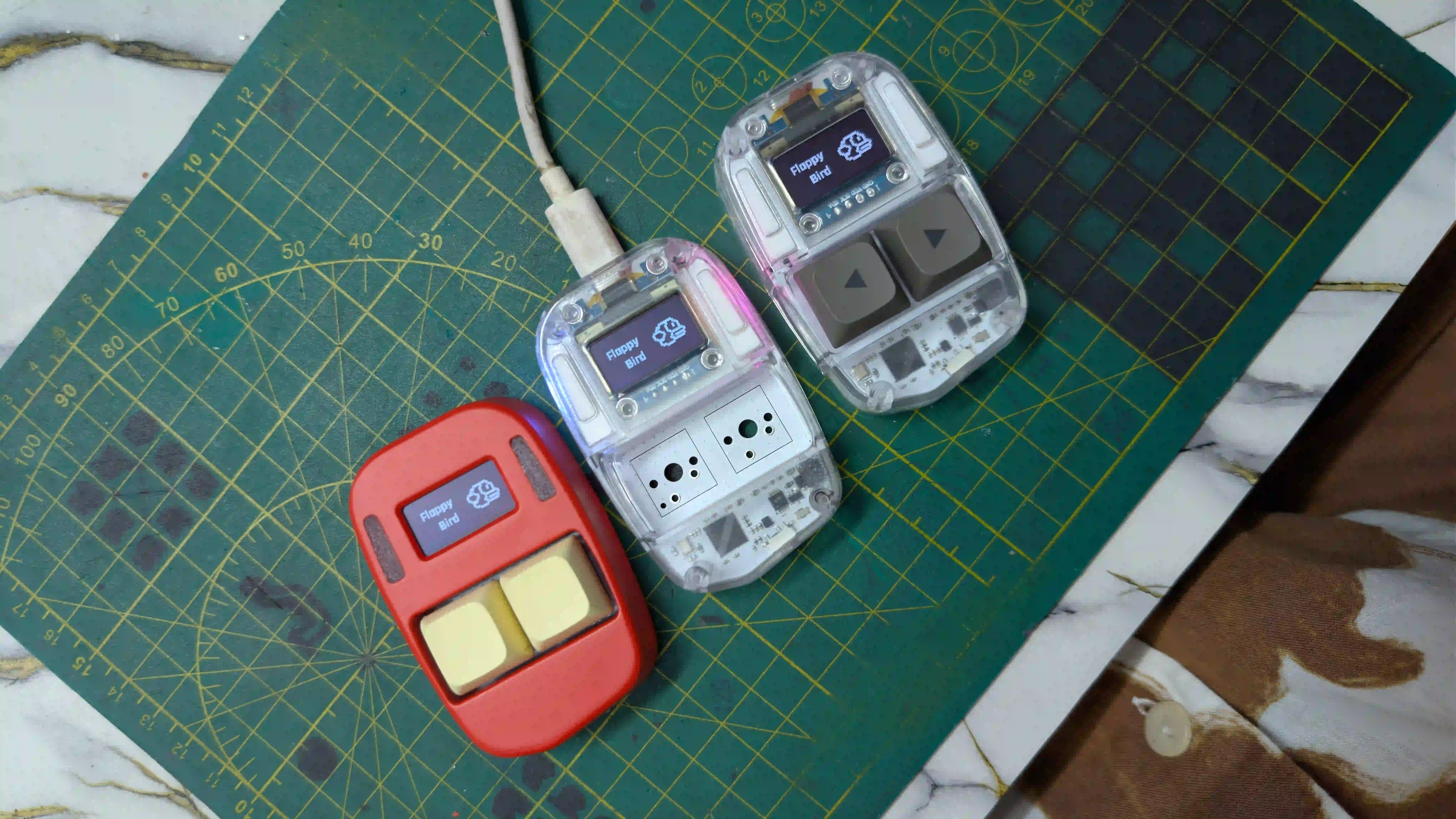
Assembling Click V4
3 Units, 1 Battery Problem, and Handing the Code Over to the Experts.
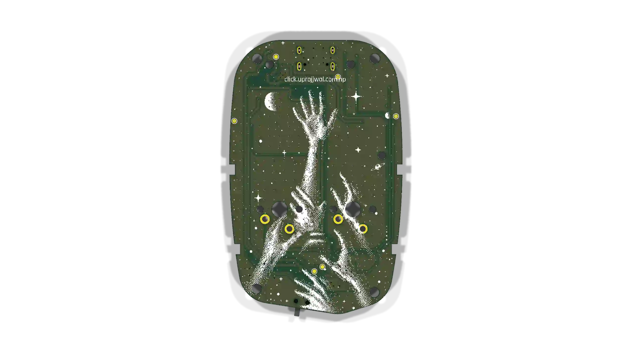
Preparing for the RP2354A
Firmware roadmap for the RP2354A board arriving tomorrow. Remapping QFN-56 pins, non-blocking state loops, 64-bit hardware IDs, and I2C sleep recovery.
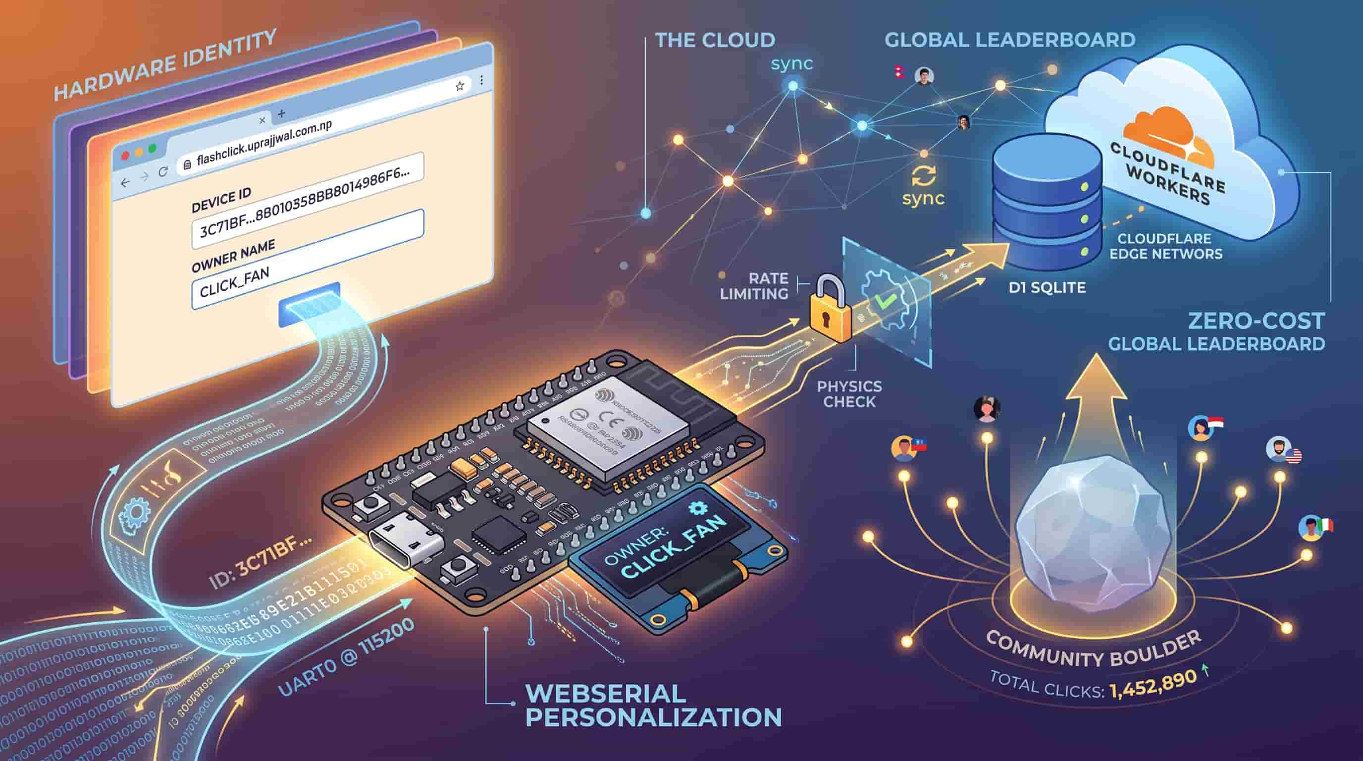
Click's Identity & the Global Leaderboard
How I connected Click's hardware identity, browser-based personalization, and a zero-cost (for now) global leaderboard.